
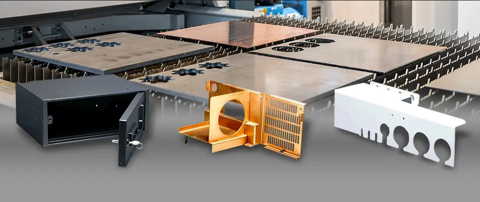
A sheet metal component can look correct on a drawing and still create trouble several steps later. A cover may refuse to close, a connector opening may appear displaced, a bracket may not sit squarely, or an assembled enclosure may show uneven gaps. In electronic products, such symptoms are often discovered only after several manufacturing operations have already been completed.
The useful question is therefore not simply whether electronics high precision sheet metal parts meet individual dimensions. Engineers also need to understand how variation moves through the fabrication sequence. Cutting, bending, joining, finishing, and assembly can each introduce a small deviation that becomes significant when combined.
When a Metal Part Becomes the Suspect
Troubleshooting usually starts at the final assembly rather than at the fabrication machine.
Suppose an electronic enclosure has a visible gap after assembly. The immediate temptation may be to inspect the overall dimensions of the panels. That is only one possible path. The real source could involve a flange, a bend location, a welded joint, or a feature that shifted during forming.
A similar situation occurs with mounting hardware. A screw hole that appears correct when measured individually may still fail to align once several formed surfaces are assembled together. The problem is not necessarily one bad dimension; it may be the accumulation of several smaller deviations.
That distinction changes how manufacturers investigate precision parts. Instead of asking whether a component is “within tolerance,” they can ask which manufacturing feature controls the observed failure.
Trace the Problem Backward From the Assembly
Electronic sheet metal fabrication commonly combines cutting, punching, bending, welding or other joining methods, fastening, and surface treatment. Each stage changes the physical state of the part.
A practical troubleshooting method is to work backward through those stages.
Start with the failed assembly condition. Identify the feature that prevents correct installation. Then determine which operation created or modified that feature. Finally, check whether an earlier operation established the reference from which the later feature was formed.
This backward chain is particularly useful for complex housings. A final misalignment may originate from a cut feature, become more noticeable after bending, and only become obvious when the completed panel meets another component. Treating the final symptom as an isolated dimensional defect can therefore lead engineers toward the wrong corrective action.
Cutting Errors Are Not Always Cutting Problems
Laser cutting and CNC punching are used to create holes, slots, openings, and other profiles in electronic sheet metal components.
Yet a questionable opening does not automatically mean the cutting operation is responsible.
Consider a slot located close to a bend. The cut itself may have the intended size and position in the flat sheet. Once the surrounding material is formed, however, the finished three-dimensional relationship can differ from what a simple flat inspection suggests. HordRT’s current sheet-metal design guidance specifically highlights hole distance from bend lines, bend relief, and practical flange dimensions as factors affecting accurate forming.
The lesson is straightforward: inspect a feature in the manufacturing state that determines its final function. A flat blank can pass inspection while the completed part still fails its assembly requirement.
Forming Can Change More Than One Dimension
Bending deserves separate attention because it converts a two-dimensional blank into a three-dimensional component.
A single bend does not only establish an angle. It also determines the position of the resulting flange, the relationship between adjoining surfaces, and the location of downstream assembly features. HordRT’s fabrication guidance notes that bend radius, hole spacing, reliefs, and flange dimensions should be considered together for accurate forming.
For electronics high precision sheet metal parts, this means dimensional control should follow the formed geometry rather than relying entirely on measurements taken before bending.
A useful troubleshooting sequence is to compare the flat pattern, formed part, and assembled condition. If the discrepancy first appears after forming, repeating the cutting inspection will not address the underlying mechanism.
Joining Introduces a New Source of Variation
Welding and other joining operations create another transition point in the manufacturing chain. Electronic assemblies may use welded structures, spot-welded components, rivets, or fasteners depending on the design.
Joining can alter how separate pieces relate to one another. A component that was individually acceptable may become problematic after it is attached to another part. The investigation should therefore examine joint location and final assembly geometry, not just the dimensions of each separate piece.
Fastened construction creates a different diagnostic path. Because fasteners can support disassembly and repair, they can also make it easier to isolate which subcomponent introduces the mismatch.
Finish and Hardware Can Create Late-Stage Problems
A part may reach the final assembly stage with its basic geometry apparently correct and still encounter an installation issue.
Surface treatment changes the finished surface condition, while added hardware changes the physical interface. Powder coating, anodizing, plating, and painting are among the finishing processes used for fabricated electronic components.
That means final verification should not stop after bare-metal fabrication. If the specification depends on the completed part, relevant features should be considered again after secondary processing.
The same principle applies to assembly hardware. A precision enclosure is ultimately judged in its finished state, not merely as a collection of individually measured metal blanks.
Inspection Should Follow the Failure Path
Quality control becomes more informative when inspection points correspond to manufacturing risk.
HordRT describes its sheet metal quality process around material and drawing review before production, cutting, bending and weld checks during production, followed by assembly fit and finish inspection.
That sequence provides a useful model for troubleshooting. Early checks establish whether the incoming material and drawing interpretation are correct. Process checks identify where geometry may change. Final inspection confirms whether the completed assembly behaves as intended.
For manufacturers producing precision electronic components, the objective is not to measure every dimension with equal intensity. It is to identify which features participate in the failure chain and verify those features at the stage where their final condition is established.
HordRT approaches sheet metal production with engineering review, fabrication, and inspection activities that can be aligned with project-specific drawings and requirements.
Ultimately, precision is easier to control when defects are treated as traceable process events rather than isolated bad measurements. HordRT’s fabrication resources cover cutting, bending, welding, and related sheet metal production processes, providing a manufacturing path in which the source of variation can be examined stage by stage.
